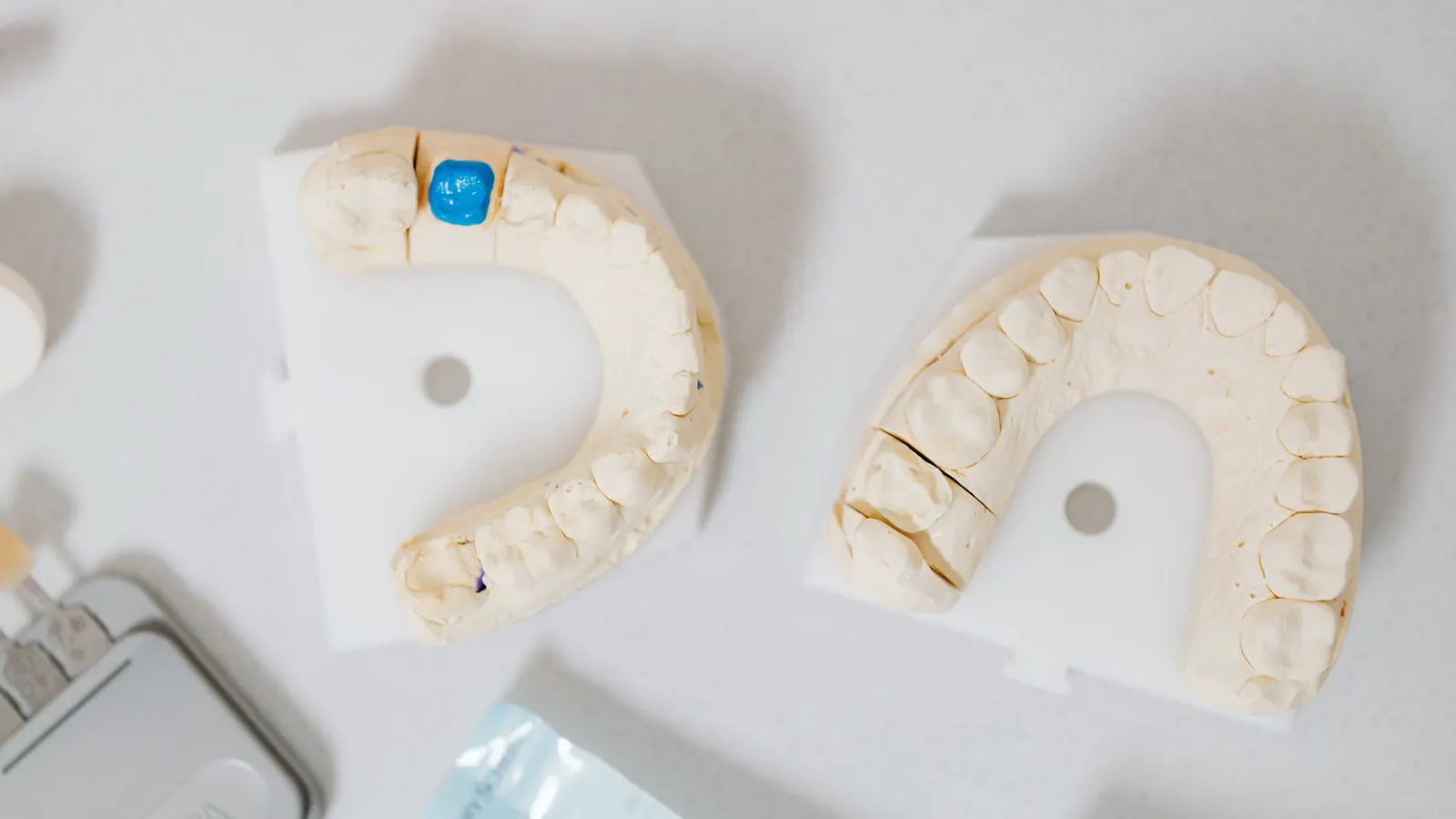
A well-designed parting line separates mold halves cleanly and hides cosmetic defects. This guide covers placement rules, draft angles, and surface preparation techniques used by professional mold designers to prevent flash and improve part appearance.
- Place the parting line where it is least visible and avoids critical surfaces like logos or front faces
- Use sufficient draft angles and undercut analysis to avoid secondary parting lines or excessive flash
- Prepare the parting surface with tight tolerances and proper finishing to match the final product appearance
- Verify the design with mold flow simulation and physical tooling checks before production
Why Parting Line Placement Drives Cosmetic Quality
A parting line separates the two halves of an injection mold and controls where material flows across the seam. Poor placement creates visible flash, weak joints, and surface marks that fail cosmetic inspection. Engineers must balance visibility, structural integrity, and material flow when selecting the seam location.
The parting line is not a single line on a drawing. It is a decision that affects mold cost, cycle time, and customer acceptance. A front-facing part may hide a seam along a side edge, while a flat panel may require a hidden internal seam or a surface treatment that masks the line.
Prerequisites Before Choosing a Parting Line Location
Before drawing the seam, gather the part geometry, material grade, and cosmetic requirements. The following inputs define the constraints for parting line design.
- Full CAD model with surface normals. Surface normals help identify which faces are front-facing and which can carry a seam.
- Material data sheet. Thermoplastics such as PP, ABS, and PA behave differently during molding. Material viscosity and shrinkage affect flash at the parting surface.
- Cosmetic spec sheet. Identify visible surfaces, critical finish zones, and any no-flash requirements.
- Assembly drawings. Parts that mate to others may require a parting line away from contact surfaces to avoid interference or marks.
- Mold flow analysis results. The simulation shows where material reaches the cavity walls first. This data helps predict where flash will form.
Step 1: Identify and Exclude Critical Surfaces
Mark all surfaces that appear on the customer-facing side of the part. These include logos, windows, handles, and any area where the part is viewed in normal use.
Exclude these surfaces from parting line candidates. If a critical surface must cross the seam, plan for a secondary process such as paint, texture, or surface treatment. However, this adds cost and complexity, so it is better to move the seam elsewhere when possible.
For a consumer electronics housing, a front bezel with a printed logo usually cannot carry a parting line. A side wall or rear surface is a better candidate. The seam should sit in a recess, a chamfer, or a non-visible edge.
Step 2: Analyze Undercuts and Secondary Parting Lines
Check the part for undercuts. An undercut is a feature that prevents a straight pull from the mold. If the parting line runs through an undercut area, the mold requires a slider, lifter, or a secondary parting line.
Secondary parting lines create additional flash risk and may leave visible marks on the part. They are also harder to clean and maintain. Designers should avoid secondary parting lines on visible surfaces.
If an undercut is unavoidable, place the primary parting line as far from the undercut as possible. Use mold flow data to confirm that the material does not force its way across an unintended seam. A secondary parting line on a hidden edge is acceptable, but one on a front face is not.
Step 3: Apply the Rule of Least Visibility
When multiple locations are structurally possible, choose the one that is least visible. This is not always the straightest or most convenient line. It is the line that disappears in the final part.
Consider the part in its assembled state. A parting line on a flange that is covered by a gasket may be acceptable. A parting line on an exposed panel is not. Evaluate the part in its final orientation, not just as a standalone CAD model.
Use a simple visual test. Imagine the part on a shelf or in a user’s hand. Which line would stand out? Place the seam where the eye is not drawn.
Step 4: Select the Parting Surface Tolerance
The parting surface is the machined face where the two mold halves meet. Its flatness and surface finish directly control flash. A rough or uneven parting surface allows molten material to escape into the gap.
Typical parting surface tolerances are tight. Engineers must specify flatness and surface finish in the mold drawing. For high-appearance parts, the parting surface is often polished to a mirror finish. For rugged parts, a lighter finish may suffice.
The parting line should not be placed on a surface that is difficult to machine flat. Complex contours or thin walls near the seam increase the risk of uneven gap pressure. Keep the seam on a flat or gently curved region when possible.
Step 5: Design for Material Flow and Flash Control
Molten plastic fills the cavity and seeks the path of least resistance. The parting line is often the path of least resistance because the mold halves are not perfectly sealed. Flash forms here when pressure exceeds the mold clamp force.
Use mold flow analysis to predict where pressure peaks near the parting line. If the simulation shows high pressure at the seam, add a parting line relief or a thin wall that reduces the gap. A small relief groove on one mold half can reduce flash without creating a visible line on the part.
The gate location also affects parting line quality. A gate placed near the parting line can push material into the seam early in the fill. A gate placed away from the seam allows the material to fill the cavity more evenly. Coordinate gate and parting line placement during mold design.
Step 6: Verify with Physical Checks
Simulation and drawing review are necessary but not sufficient. Physical checks confirm that the parting line behaves as designed.
- Inspect the mold parting surface. Check for machining marks, dents, or uneven gaps. A single scratch can create a visible line on the part.
- Perform a test shot. Run the mold at production parameters and inspect the part for flash along the seam.
- Check assembly fit. If the part mates to other components, verify that the parting line does not interfere with the assembly.
- Review cosmetic samples. Compare the part against the cosmetic spec. A line that is acceptable on a prototype may fail on a finished part.
If flash appears, do not simply increase clamp force. Adjust the parting surface finish, add a relief, or move the parting line. Increasing clamp force alone masks the problem and does not fix the root cause.
Common Mistakes in Parting Line Design
Parting line design failures usually stem from a few recurring errors. Review these mistakes before finalizing the mold drawing.
| Mistake | Consequence | Correction |
|---|---|---|
| Parting line on a visible front face | Visible seam and flash | Move seam to a hidden edge or recess |
| Ignoring secondary parting lines | Additional flash and marks | Redesign to avoid undercuts near the seam |
| Loose parting surface tolerance | Uneven flash and rough surface | Specify tight flatness and polish the surface |
| Gate placed near the parting line | Early fill and pressure buildup | Move gate away from the seam area |
| No mold flow analysis | Unpredicted flash locations | Run simulation before tooling |
| Parting line on a thin wall | Weak joint and high flash risk | Place seam on a thicker section |
Final Verification Before Tooling
Before releasing the mold drawing, perform a final verification. Confirm that the parting line satisfies all cosmetic, structural, and manufacturing requirements.
- Check the parting line against the cosmetic spec. Every visible surface should be free of the seam or have a planned treatment.
- Review the mold flow analysis. Confirm that no secondary parting lines appear on visible areas.
- Validate the parting surface tolerance. Ensure the drawing specifies the correct flatness and finish.
- Confirm gate and parting line compatibility. The gate should not create a direct pressure path to the seam.
- Approve the physical check plan. Schedule a test shot and cosmetic review after tooling.
A parting line is a design decision, not a default feature. It shapes the appearance, strength, and manufacturability of the final part. Engineers who treat it with the same attention as the cavity geometry produce molds that reduce flash, lower cycle time, and meet cosmetic standards without secondary processing.
The final step is not just a sign-off. It is a confirmation that the seam will behave as intended in the mold, on the part, and in the customer’s hands. If the design passes these checks, the parting line becomes an invisible detail rather than a defect source.
Frequently asked questions
Can a parting line be hidden inside a part?
Yes, if the part has a recess or an internal cavity, the seam can be placed inside that area. The line must still be machined on the mold, but it will not appear on the external surface.
What happens if the parting line is placed on a thin wall?
Thin walls create high pressure at the seam during filling. This increases flash risk and can weaken the joint. Place the parting line on a thicker section when possible.
Do all materials require the same parting surface finish?
No. High-viscosity or low-melt materials may show flash more easily on a rough surface. Polished or polished-to-fine-finish parting surfaces reduce flash on most thermoplastics, but the exact finish depends on the material and part appearance.
Is mold flow analysis enough to prevent parting line flash?
No. Simulation predicts risk, but physical mold conditions matter. The parting surface finish, mold wear, and clamp force all affect actual flash. Use simulation to guide design, then verify with a test shot.
Can a parting line be added after the mold is made?
Adding a parting line after tooling is difficult and costly. It may require re-machining the mold halves or adding a relief. It is far better to define the parting line during the mold design phase.